Entorquer-KvL-TQ202 / KVL-TQR202USB

Description
Entorquer-KvL-TQ202 / KVL-TQR202USB is Our simplest radio control device. It can communicate with the Cordless clutch shut off Tools integrated with our radio module.
The controller communicates with the PLC via I/O. The PLC can enable or tilt the device, and the OK / Not OK or the Reverse screwing signal is also returned to the PLC via I/O.
Easy to install
The TQR202- modules were designed for fast installation and maintenance. If any issues arise, the modules can be replaced in one minute or less.
Simple device pairing
To pair the transmitter and the receiver, simply press the receiver button and insert the battery for Cordless shut off tool.
Multiple Operating Modes
The device can default to its normal mode, or disabled mode. If normal mode is enabled by default, the device can be disabled at any time, to avoid errors.If the tool is in disabled mode by default, meaning that it cannot be engaged before or after the assigned assembly operation.
In sleep mode
The Radio module will switch off automatically when the device is left idle, to conserve battery life. The radio module will wake up from sleep mode immediately if it is moved.
In Link Mode
The device will detect whether it is near the receiver. If not (the device is used outside the usual work environment), it can be disabled.
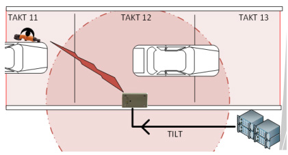
Typical usage (example from a car manufacturing plant) The following is an example of the device in use, in a car manufacturing plant The operation will wait for the car to approach his/her work location. The tool is in disabled mode by default, meaning that it cannot be engaged before or after the car assembly. This can cut down on damage due to improper use. See Fig. 1. The line PLC (Line control device) Disables the TQR202, using the Disable Input. This ensures that the worker will not be able to use the tool until the car reaches the correct position.
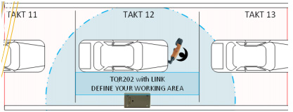
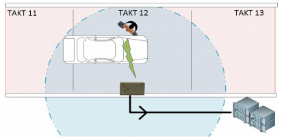
As can be seen on the Fig 2, the Line PLC (Line control device) then enables the tool, allowing the operator to begin working. The device can then be positioned to work anywhere within the blue circle. The blue circle depicted is only an example, and can be modified by using our configuration program. Should the operator leave the circle, the “Link” option will tilt the device, disconnecting it.
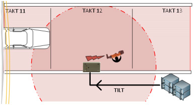
Beginning the work process, the operator starts tightening Fig 3. All tightening feedback, including OK / not OK or Reverse tightening, is immediately sent back to the Line PLC for evaluation. Once the number of tightening processes performed reaches the number assigned to the work process in question (for example, if the operator is tasked with tightening 5 screws, then once 5 OK tightening signals are sent to the PLC), the line PLC can disable the device again, to avoid possible damage from improper use.
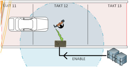
The worker try to work on the next car Fig4, but because the tool is in disabled mode, it is not possible. It will be only possible, when the device get an enable signal from the Line PLC.
We are open to custom-developing solutions for you with our partners, using our specific screwdriver data collection system. This will allow you to control all necessary tightening tasks and get customized data for analysis to ensure error-free, efficient operations. If you are interested, please do not hesitate to contact us.